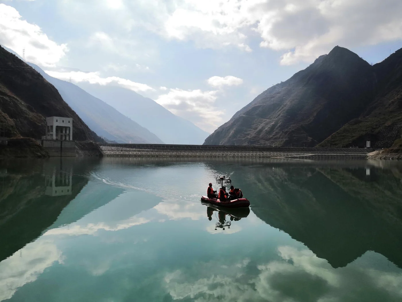
Reservoir surveying in a mountainous landscape

APPLICATION / HYDROGRAPHIC SURVEYING

Positioning & Attitude for Hydrographic Surveying

Position, roll, pitch, heading and heave for vessel-based multibeam surveying: navigation inputs for georeferencing measurements and compensating for vessel motion.

Discuss your survey setupFIELD PHOTOGRAPH / RESERVOIR SURVEY

THE ROLE OF NAVIGATION

A reference within the measurement chain.

The IMU and dual GNSS antennas feed navigation processing. Its position and motion outputs support the survey equipment, alongside sonar, acquisition software and the geometry of the complete installation.

Illustrative data flow. RAYSEN provides the navigation system and related integration support; sonar, acquisition and survey processing remain parts of the wider measurement setup. Confirm message formats, output rates, interfaces and time synchronization for the connected equipment.

ASSESS YOUR SETUP

Match the navigation to the task.

Use the measurement requirements and vessel conditions for a first fit assessment. Product and integration details carry the model-specific information.

Required data
Identify the position, roll, pitch, heading and heave your receiving equipment needs, including the expected data flow.
Review system outputs
Accuracy & conditions
Assess GNSS aiding, antenna separation, installation geometry and operating conditions. Compare model figures under their stated GNSS conditions.
Compare models
Connections & timing
Confirm equipment and software models, message formats, output rates, interfaces and synchronization requirements together.
Review integration
Installation geometry
Review antenna sky visibility, rigid mounting, lever arms, installation angles and available space aboard the vessel.
Plan the installation
Application-specific work
Adaptation and targeted R&D address application needs, target accuracy and operating conditions alongside interfaces, space and outputs.
Explore engineering

Rivers, bridges & reservoirs

Review the platform layout, GNSS visibility and installation geometry. The Jiujiang record shows one specific bridge-area measurement task.

Harbour basins & quays

Plan the equipment combination, calibration, acquisition and output review. The Bangkok record follows these steps in a harbour-basin demonstration.

Coastal & nearshore waters

Assess the onboard installation and operating conditions, including the vessel layout, sensor mounting and requirements of the survey task.

RELATED APPLICATION RECORDS

From installation to survey outputs.

Two 2019 records show navigation within combined multibeam workflows, with documented configurations, field procedures and measurement outputs.

Historical application record

Bridge-Pier Multibeam Survey in Jiujiang

Survey the underwater bridge-pier area and riverbed approximately 200 m upstream and downstream of Jiujiang Second Yangtze River Bridge.

Configuration
iPos MS11 · iBeam8120 · Swiftsvp sound velocity profiler

Measured sensor offsets, installation calibration and cross-sections accompany the 3D point cloud around pier 22.

A documented application of iPos MS11 in a bridge-area multibeam survey.

Read the Jiujiang survey record
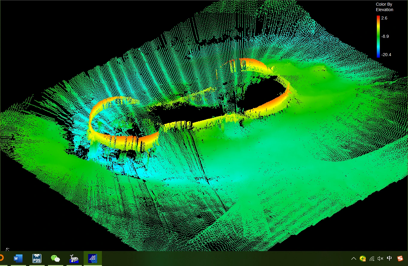
Three-dimensional point cloud showing the underwater area around bridge pier 22
Three-dimensional point cloud around pier 22. The view shows the surveyed underwater geometry.
Field demonstration

Multibeam Survey Field Demonstration in Bangkok

Demonstrate a combined navigation and multibeam survey workflow in a Bangkok harbour basin, from installation and calibration to acquisition and terrain review.

Configuration
iPos MS11 · iBeam8120 multibeam system

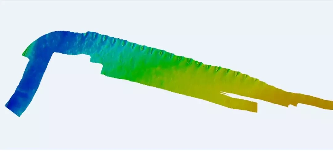
Calibration profiles, 3D terrain outputs and a reciprocal-line consistency check document the measurement workflow.

The field record describes RaysenNav participation in installation, commissioning and workflow demonstrations.

Read the Bangkok demonstration record
Colour-coded three-dimensional terrain model from the Bangkok harbour-basin survey
Terrain output generated in HiMAX MBE from the harbour-basin survey data.
STANDARD PRODUCT SELECTION

Explore iPos MS.

Select the deck unit, IMU and dual GNSS antenna configuration around your position, attitude, heading and heave requirements. Review the target accuracy, GNSS conditions and vessel installation before choosing a model.

Compare models & configurations
ADAPTATION & DEVELOPMENT

Adaptation & application-specific R&D

We provide adaptation and targeted R&D for your application, accuracy goals and operating conditions, including interface, space and output requirements. Project assessment defines the specific work and validation approach.

Explore custom engineering

PREPARE YOUR INTEGRATION

Start with the working conditions.

You don’t need a complete specification to start. These details help make the first conversation useful.

  • 01

    Task & platform

    Survey object, vessel or platform, water environment and project stage.

  • 02

    Outputs & performance

    Position, roll, pitch, heading and heave requirements, with the known operating conditions.

  • 03

    GNSS & installation

    Satellite visibility, antenna separation, mounting locations, available space and sensor geometry.

  • 04

    Connections & synchronization

    Survey equipment and software models, output formats, interfaces and time synchronization requirements.

ENGINEER TO ENGINEER

Tell us about your survey setup.

Share your vessel, survey equipment and key requirements to begin the integration discussion.

Discuss your survey setup